


")

ULN2003 IC is one of the most commonly used Motor driver IC. This IC comes in handy when we need to drive high current loads using digital logic circuits like Op-maps, Timers, Gates, Arduino, PIC, ARM etc. For example a motor that requires 9V and 300mA to run cannot be powered by an Arduino I/O hence we use this IC to source enough current and voltage for the load. This IC is commonly used to drive Relay modules, Motors, high current LEDs and even Stepper Motors. So if you have anything that anything more than 5V 80mA to work, then this IC would be the right choice for you.
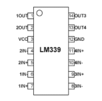
The ULN2003 is a 16-pin IC. It has seven Darlington Pairs inside, where each can drive loads up to 50V and 500mA. For these seven Darlington Pairs we have seven Input and Output Pins. Adding to that we can a ground and Common pin. The ground pin, as usual is grounded and the usage of Common pin is optional. It might be surprising to note that this IC does not have any Vcc (power) pin; this is because the power required for the transistors to work will be drawn from the input pin itself. The below circuit is a simple circuit that can be used to test the working of ULN2003 IC.
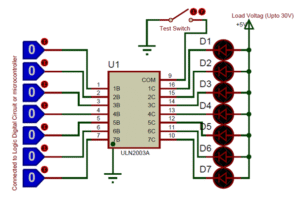
In the circuit consider the LED to be the loads and the logic pins (blue colour) as the pins connected to the Digital circuit or Microcontroller like Arduino. Notice that the Positive pin of the LED is connected to the positive load voltage and the negative pin is connected to the output pin of the IC. This is because when the input pin of the IC gets high the respective output pin will get connected to ground. So when the negative terminal of the LED is grounded it completes the circuit and thus glows. The loads connected to the output pin can be maximum of 50C and 500mA each. However you can run higher current loads buy combining two or more output pins to gather. For example if you combine three pins you can drive up to (3*500mA) ~1.5A.
The COM pin is connected to ground through a switch, this connection is optional. It can be used a test switch, meaning when this pin is grounded all the output pins will be grounded.
The ULN2803 is a Darlington array IC it can be used to drive Stepper and DC Motors, Relays, Solenoids, and other external circuits operating at high voltages and currents from simple CMOS logic signals from microcontrollers. It has 8 driving channels, each channel can withstand peak currents of 600mA. Suppression diodes are included for back EMF protection while driving inductive loads. The ULN2004 is used in the current version of our 8 Channel Relay Board to drive the onboard relays.
Applications
Used to drive high current loads using Digital Circuits
Can be used to drive Stepper motors
High current LED’s can be driven
Relay Driver module (can drive 7 relays)
Logic Buffers in digital electronics
Used as Touch sensor for Arduino
Related Products

Reviews
Clear filtersThere are no reviews yet.